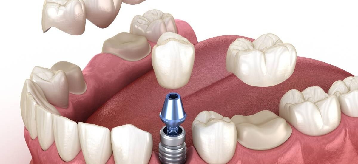
Connector size in bridge design is the quiet variable that decides whether a case serves a patient for a decade or returns fractured within the first year. Nobody frames a remake poster on the lab wall. Still, every technician remembers the bridge that snapped at the pontic junction. Because the connector sits between the retainer and the pontic, it is also the easiest part of a design to leave on autopilot. That is exactly where strength quietly goes missing.

What the Connector Actually Carries
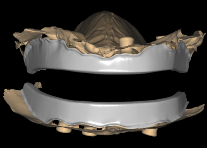
A connector behaves like the web of an I-beam. Chewing loads flex the whole framework. The highest bending stress collects right where the pontic meets the retainer. If that cross-section is too small, the stress has nowhere to go. The material eventually gives up, usually through a fatigue crack that grows a little every day until one breakfast changes everything.
Height matters more than width here. A taller connector resists bending far better than a wider one of the same area. That is the same reason an I-beam stands on edge. So when vertical space is tight, the first instinct should be to gain connector height toward the occlusal surface. Widening the contact indiscriminately into the embrasure is the weaker fix.
The scan sets the ceiling. If the die or the ridge area is fuzzy at the junction, the designer ends up estimating geometry instead of measuring it. Clean records give the connector room to be sized correctly from the start, and they make every later check faster.
Bending, Not Just Compression
It helps to picture the connector as two halves. One side works under compression and the other under tension. Ceramic materials handle compression well but are far less forgiving in tension. For that reason, a thin section on the gingival side of a zirconia connector is the classic fracture starting point. When you review a design, look at the gingival surface first. That is where the failure usually begins.
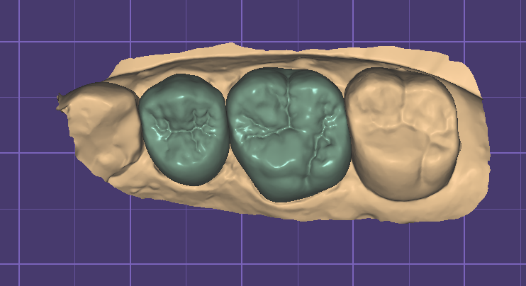
Connector Size Rules by Material and Span
There is no single magic number. The minimum cross-section depends on the material’s flexural strength and its fracture toughness. The span then multiplies the load. A three-unit posterior bridge and a five-unit anterior case do not live under the same rules, even when the material is identical. The safe approach is simple. Start from the material, adjust for the span, and treat every guideline as a floor rather than a target.
Commonly Cited Minimums for the Main Materials
Across the industry, these figures come up again and again as starting points for three-unit cases:
- Monolithic zirconia: around 9 mm² of connector cross-section is the commonly cited minimum for posterior work, with more area preferred as the span grows.
- Lithium disilicate: roughly 12 mm², which is one reason glass-ceramic bridges are usually kept to three units and why premolar spans get extra caution.
- PFM and full-cast alloys: smaller cross-sections around 4 to 6 mm² can work because metal bends before it breaks, but ductility is not a licence to design thin.
Treat those numbers as orientation, not gospel. The manufacturer’s instructions for use always win. A material batch, a sintering schedule or an aggressive occlusal scheme can all shift the real-world answer. If you want a broader engineering context, the overview of fixed prosthodontics on Wikipedia explains why connector geometry has limited bridge work since the earliest days of the discipline.
Where Labs Lose Strength in Practice
The guidelines above rarely fail on paper. They fail in the everyday details of a real case, and the pattern is consistent enough to list.
First, aesthetics eats connectors. A designer asked for open embrasures and papilla-friendly shaping can carve away cross-section millimetre by millimetre. The junction looks fine on screen but measures under the minimum in reality. Second, short pontics in the lower anterior region leave almost no vertical room. The connector lands in the one place the anatomy cannot support. Third, span creep. A case prescribed as three units quietly becomes four during design, and nobody re-runs the connector math. Each of these is a workflow problem before it is a materials problem.
Documentation keeps this honest. When the prescription, the material and the connector dimensions are written down before design starts, there is no room for a quiet compromise in the middle. Labs that track remakes by cause rarely list connectors as the stated reason. The case gets logged as a fracture, which hides the sizing decision made weeks earlier. That is worth remembering the next time the remake numbers are reviewed.
Short Pontics and Reduced Vertical Space
When interocclusal space is tight, the honest options are limited. You can adjust the connector shape rather than its area. You can move the junction slightly toward the occlusal to buy height. You can also push back on the prescription. Guessing is the expensive option. A design partner should flag the constraint before the file ships, because a connector that meets the number only on paper is still a remake waiting for a calendar slot.

How We Check Connector Design Before Delivery
At OdontaLab, connector size in bridge design is part of the standing protocol rather than a per-case improvisation. Your lab tells us the material system, the mill and the span limits once. We store those rules against your account alongside spacer values, minimum thickness and contact gauge. Every crown and bridge case that follows arrives pre-configured. A five-unit zirconia case never gets treated like a single crown.
Each file also passes a senior quality check before release. The check covers the connector area explicitly: cross-section against the material floor, position against the ridge, and embrasure shape against the prescription. If a margin, an occlusion or a connector constraint looks wrong, we flag it and ask instead of guessing. Standard turnaround stays at 12 to 24 hours from complete records. Minor revisions are free until the design is approved.
If your lab would rather not gamble on the junction that holds a bridge together, our crown & bridge design service bakes these checks into every case. You can also browse the full design catalogue or send a test case and judge the file quality on a real job from this week.