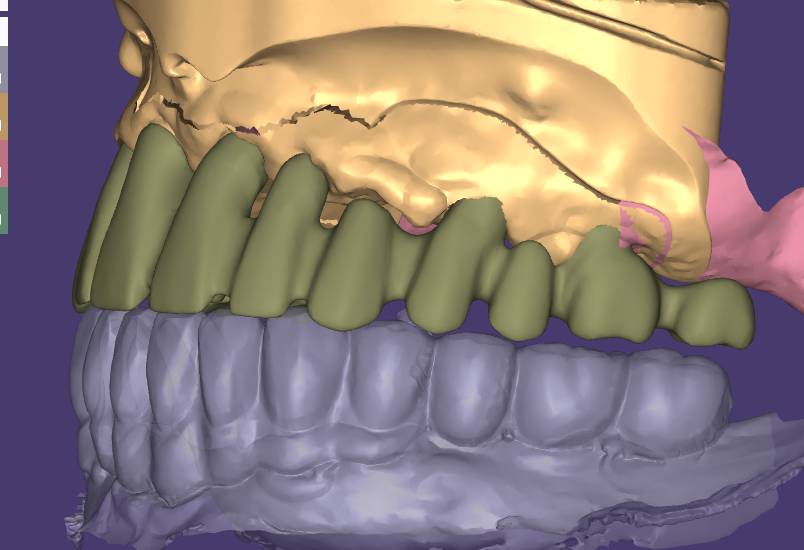
PFM coping design sets the ceiling on how good a porcelain-fused-to-metal crown can be. The ceramic gets the praise at delivery, yet the metal substructure underneath carries the load for years. When the coping is right, the porcelain sits on even support and the crown seats without drama. When it is wrong, you see chipping, open margins, and remakes that wipe out the profit on the case. Your mill never sees these decisions, but your remake shelf does. This guide covers the three checks that decide the outcome: wall thickness, ceramic cutback, and fit.
A PFM crown is a two-material system. The alloy provides strength and retention. The porcelain provides esthetics and a tooth-friendly wear surface. The bond between them is part mechanical, part chemical. It lives or dies on three decisions made at the design stage. First, the coping geometry has to support an even layer of ceramic. Second, the junction between metal and porcelain has to stay smooth and away from occlusal contacts. Third, the margin has to seat so the cement line remains thin and sealed. Miss any one and the failure is predictable. You get fracture at the interface, or a leaking margin months later.
Wall Thickness: The Numbers That Keep Ceramic Alive
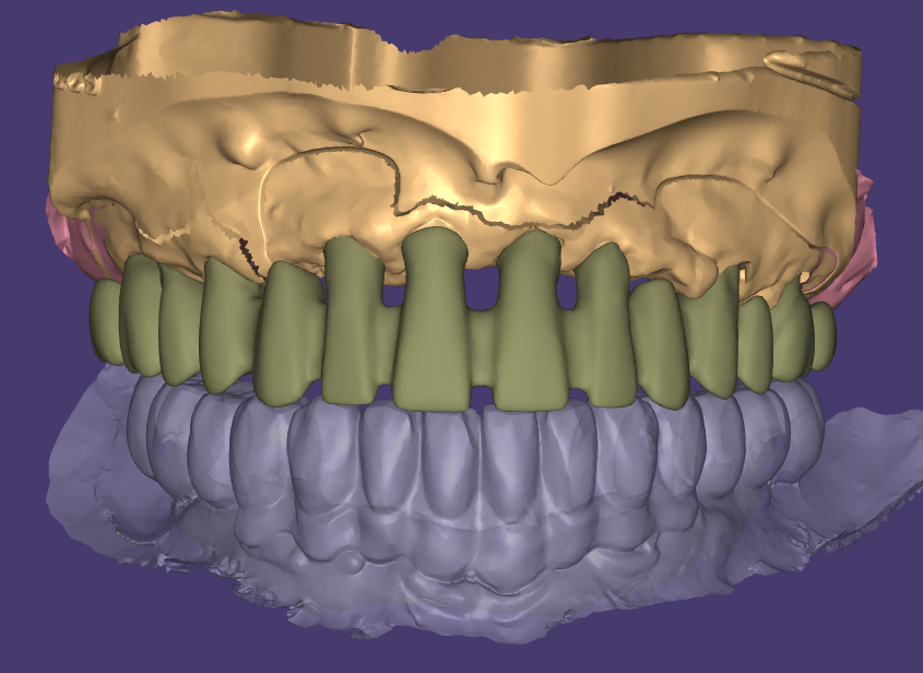
Under the porcelain, most alloy systems want at least 0.3 to 0.5 mm of metal. Thinner walls flex during the firing cycle. Flex means the ceramic cools under stress, and stress is where chips begin. For that reason, we design above the minimum for the alloy named on your prescription. No generic defaults. Base-metal and noble alloys behave differently at temperature, so the coping follows the material your lab actually casts.
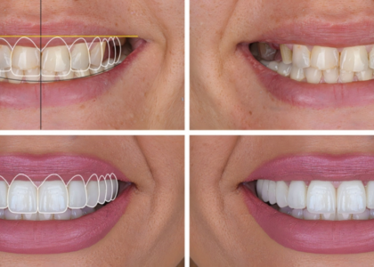
Thickness cuts in both directions. A bulky coping steals room from the porcelain, so the finished crown comes out over-contoured or starved of ceramic. As a rule of thumb, aesthetic zones want roughly 1.2 to 1.5 mm of porcelain over metal. The exact value depends on the system, so we confirm it against your prescription. Before any file leaves our studio, we confirm those numbers against your fabrication protocol. The coping should fit your furnace as well as your die.
Cutback: Support the Porcelain, Not Starve It
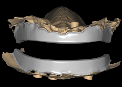
The cutback is where PFM coping design gets subtle. The designer first builds full-contour anatomy, then cuts it back to create room for porcelain. Cut back too little and the veneering ceramic ends up paper-thin, so it chips under load. Cut back too much and the porcelain is thick but unsupported, so it fails from within. The target is an even, supported layer with a gradual transition at the metal-ceramic junction.
The junction line and occlusal contacts
A good junction is rounded, smooth, and placed away from the opposing tooth. Sharp corners act as crack starters, and contacts on the junction line are a classic chipping point. So the design keeps porcelain-to-metal borders clear of centric and excursive contacts. Where your protocol calls for a metal occlusal, the cutback stops short and the functional surface stays in alloy. If your team wants the material background, the Wikipedia overview of dental porcelain covers the metal-ceramic bond well.
Margins and Fit: Where Remakes Start
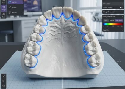
Margins cause more remakes than fracture ever will. A PFM margin can be all metal, all porcelain, or a combination. Metal margins are forgiving and easy to check on the die. Porcelain butt margins look better on anterior cases, but they demand a clean, well-defined margin line from the scan. Either way, the margin gets traced on the model edge by edge. No auto-detection line goes out unreviewed.

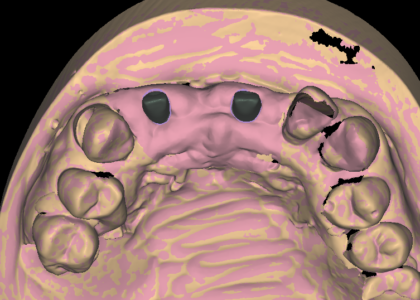
Unclear margins are flagged, never guessed. If a section of the margin is fuzzy or short, the case goes back to your team. You get a screenshot and a question before the design moves forward. That habit sounds small, yet it prevents more remakes than any other single step on our bench.
Cement space and seating
Cement space is the quiet half of fit. The spacer setting has to match two things. One is the cement your lab plans to use. The other is the way the alloy behaves in casting. The margin zone stays tight per your protocol while the body gets relief. Once the spacer is set for the material, seating gets easy. The crown finds its seat at try-in without grinding, and the cement line seals instead of hiding a gap.
How We Run PFM Coping Design at OdontaLab
OdontaLab is a dental CAD studio in Shenzhen. We design for laboratories across North America, Europe, Australia and the Middle East. PFM coping design is a daily case type on our bench. Zirconia copings, crown and bridge work, and implant restorations fill the rest of the queue. Every case is designed in exocad or 3Shape to your margin type and spacer protocol. A senior designer checks it again before delivery. Standard turnaround is 12-24 hours, and minor revisions are free until you approve the design.
What to send with the case
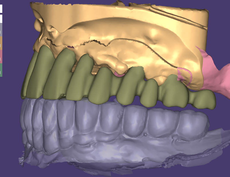
The recipe is short. Send three things. First, the prep or model scan with a marked margin line. Second, the opposing arch with a bite record. Third, your material choice. If your lab has standing parameters, we store them on your account. Future copings then arrive pre-configured for your mill and alloy. The full scope of the service sits on our PFM Coping Design page. You can also browse every design service we offer in one place.
If coping backlog is slowing your bench, test us with one real case. Send the scans through our contact page with your margin specification. We will confirm the design path and delivery time before we start.