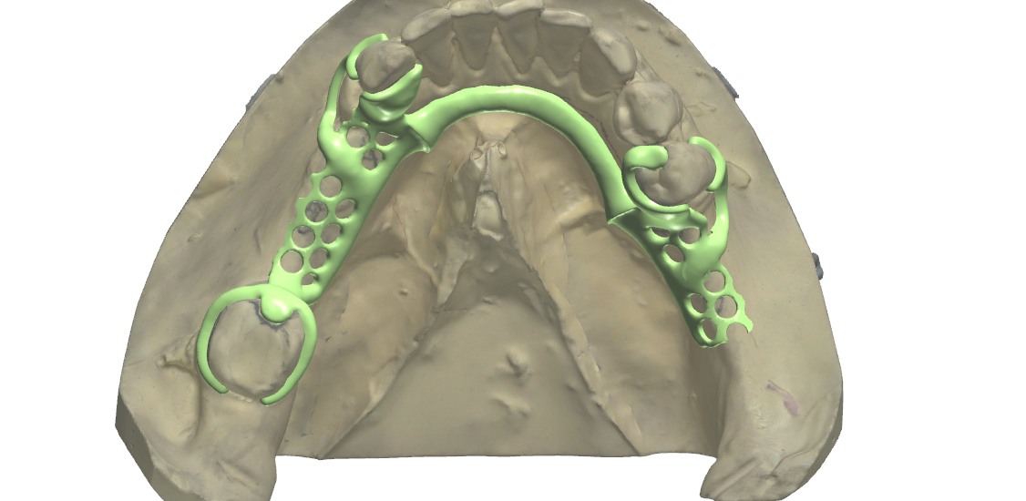
Metal framework design is won or lost before anyone touches a clasp. The moment you settle the path of insertion, most of the case is already decided. Which undercuts can hold retention? Where do the guide planes run? Will the framework seat with light finger pressure, or fight you chairside? Because so much rides on that early call, this article walks through the survey, the path, and the settings in between. The goal is simple: a scanned cast that becomes a partial your bench can finish in one pass.
Fit problems on a removable partial rarely start at the bench. They start in the design file, weeks earlier, with a tilt that looked fine on screen. The upside is that a digital survey gives you more control than any desktop surveyor ever did. You just have to use it deliberately instead of accepting the default view.
Metal framework design starts with the survey
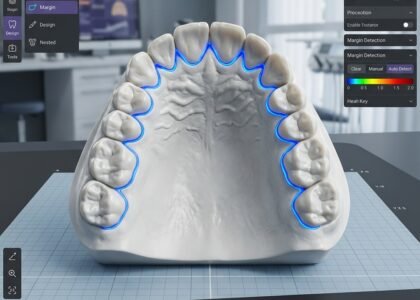
Every case begins with a question: which way should this cast tilt? The digital surveyor in exocad or 3Shape answers it the same way a physical one would. You rotate the cast and watch the undercuts migrate. Then you hunt for a position that gives the abutments useful retention. Along the way, you keep hard interference away from the planned connectors.
Read the case before the software does. Look at the anterior segment and the soft tissue contour first, since the major connector often crosses that area. Then tilt toward the side that gives the arch enough opposed undercuts for the clasps you actually want. If the tilt hands you perfect retention on one side and nothing on the other, take the hint. The survey is telling you to rethink the clasp plan rather than force it.
Choosing the path of insertion
A path of insertion has two jobs, and they pull in opposite directions. It must let the prosthesis seat along one direction, and it must resist dislodgment along another. For a typical distal extension case, the winning tilt often points toward the saddle area. That way, the mesial undercuts engage on the way in while the distal surfaces stay free for bracing. For a tooth-bounded span, a single parallel path with modest bilateral retention usually beats a dramatic tilt.
Once you fix the path, lock it down. Record the tilt, note it in the case documentation, and keep every later decision inside that reference frame. Teams that re-survey casually at the block-out stage end up with guide planes that no longer parallel the path. That mismatch is a quiet way to build binding into an otherwise clean file.
What the path of insertion decides
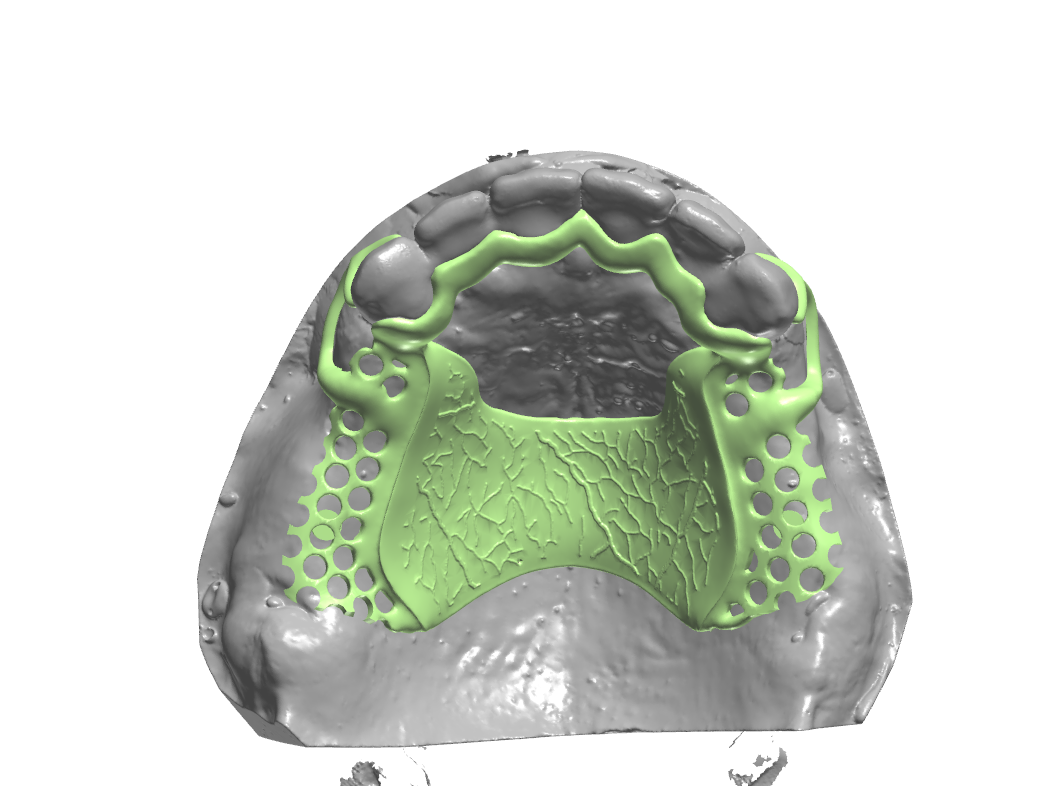
The path drives three outcomes at once. Retention comes from undercut engagement near the clasps. Reciprocation and bracing come from surfaces that stay in contact on the opposite side. Stability comes from guide planes that resist lateral movement. Because all three live on the same tilt, a change to one changes the others. So it pays to know which problem you are solving before you move the cast again.
Retention, support and bracing
Clasp selection falls out of the survey almost automatically afterwards. A gingivally approaching I-bar suits a visible tooth with a shallow undercut. A cast circumferential clasp takes a deeper, more defined undercut and dislikes soft contours. Ring clasps, RPI designs and combination clasps each ask for specific undercut depths in specific positions. So read the survey numbers before you pick the arm, not after.
Rest seats matter just as much, although they get less attention. Occlusal and cingulum rests define where load transfers into the abutment, and their geometry depends on the tilt too. If the path drifts late in the design, rests that looked correct can end up sloped. The finished framework then loads the abutment in shear instead of compression.
Block-out, relief and your production method
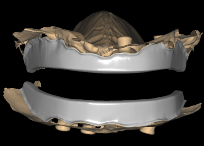
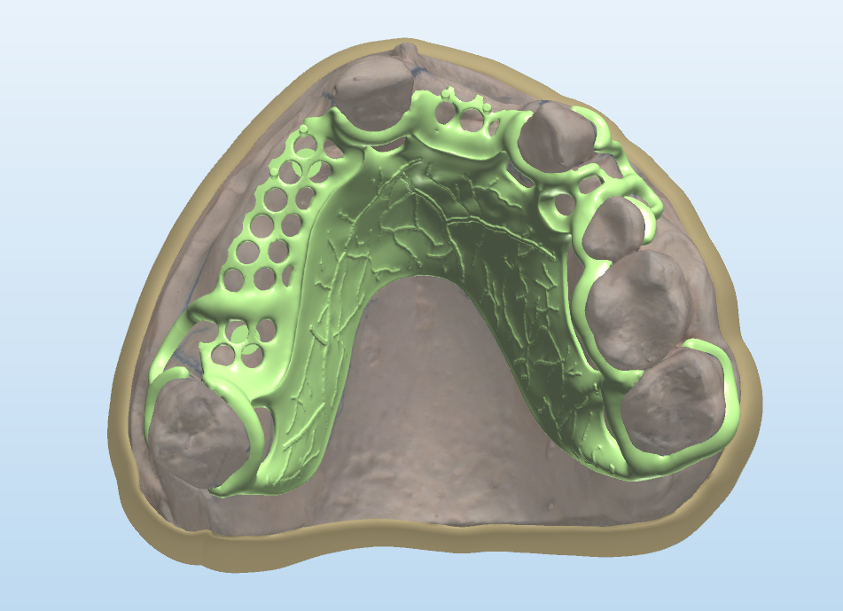
With the path fixed, block-out and relief translate the survey into a manufacturable file. Undercuts that sit outside the path of insertion get blocked out so the framework can seat. Undercuts inside the path stay open for retention. Relief under the major connector and across the ridge depends on the tissue. It also depends on how the case will be made, and that difference matters more than most settings pages admit.
A cast chrome-cobalt framework wants tissue relief tuned for the casting cycle. Add a little extra where the connector crosses a bony prominence. A milled or printed framework holds tighter tolerances, so identical relief values can leave it floating. For that reason, keep a saved profile per production route. Your relief values, connector minimums and expansion allowances should follow the material rather than the mood of whoever designs that day.
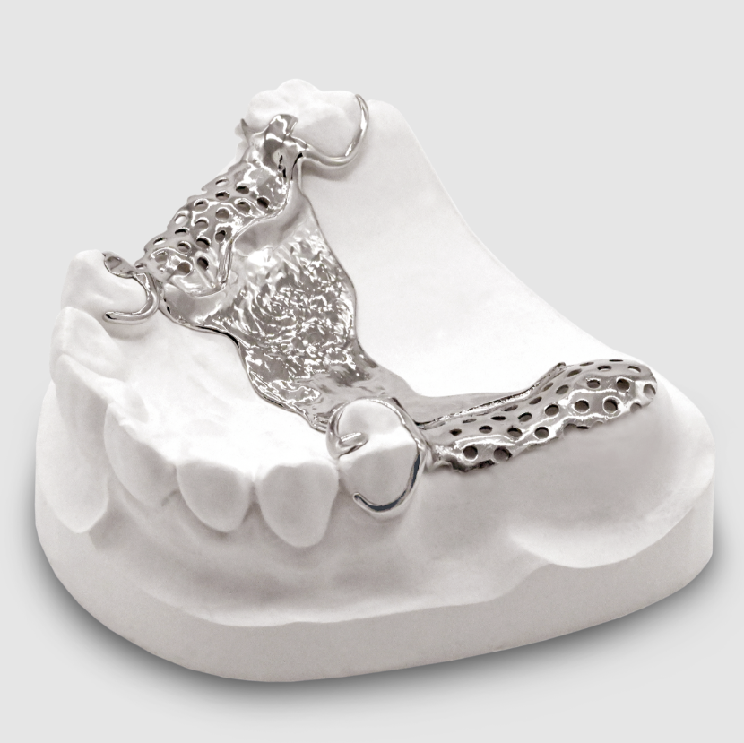
Guide planes deserve a final pass as well. Trim them parallel to the path, wide enough to brace, and short enough to avoid binding on insertion. When a lab skips this step, the patient still gets the framework in. Every removal afterwards, though, scrapes the same abutment. That wear pattern is the signature of a guide plane that never quite matched the path.
How outsourced metal framework design works at OdontaLab
None of the steps above are exotic. They do take survey discipline and bench time, and many labs cannot spare either during a busy week. That is where our Metal Framework Design service fits in. Send the master cast scan with your survey noted. Or let us run the survey digitally and flag the undercuts and block-out requirements for you. We design to your clasp plan, connector style and material. Every framework comes back within 12 to 24 hours, with the path of insertion documented.
Quality control sits behind the delivery too. A senior designer reviews every file before it reaches your queue. The check covers connector cross-sections against the span and the alloy, relief against the casting or milling route, and clasp passivity against the survey line. If your prescription is unclear, we ask first, because one message beats one remake. Minor revisions stay free and unlimited until you approve the design.
If you want to test the workflow on a real case, send one through our case submission page with the cast scan and your material choice. For a broader look at the studio, the services overview lists all fourteen design lines, from crown and bridge to implant bars. For the clinical background behind partial denture planning, the removable partial denture entry on Wikipedia is a solid refresher. Frameworks reward the labs that respect the survey, and every good survey starts with one honest tilt.