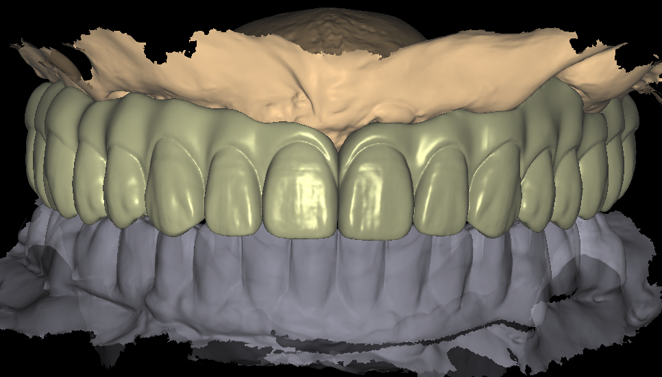
Screw-retained crown design is a channel problem before it is a crown problem. The screw path decides wall thickness, occlusal anatomy, and whether the restoration can come off later without being cut away. Laboratories that treat the channel as an afterthought tend to meet one of two endings. Sometimes the design mills cleanly and seats badly. Sometimes the access hole lands where the patient notices it every time they smile.
None of that is a software problem. It is a planning sequence, and the order matters. A designer who places the channel first and builds anatomy around it avoids most remakes. A designer who sculpts a nice crown and then looks for room to drill usually starts over. The sections below follow that sequence. Hand the same logic to your bench or to a design partner and the conversation gets shorter.
Why the Screw Channel Comes First
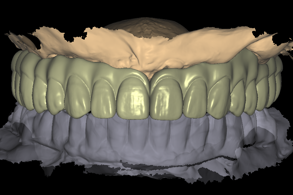
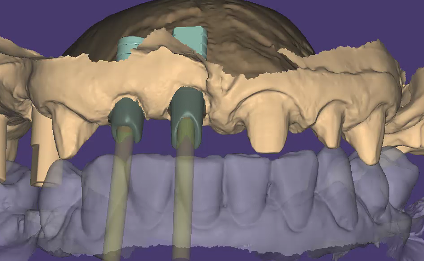
The implant sets the axis, and the crown has to live with it. In the anterior maxilla that often means a slightly facial implant. Its screw path wants to exit through the labial surface. From there a designer has three moves. Keep the channel straight and accept where it lands. Correct the channel toward the cingulum. Or propose a different retention method for the case. Each choice changes the material budget further down the line.
Straight channels stay the simplest and the strongest option. The screw seats fully, torque transfers the way the manufacturer intended, and the access hole stays compact. That works whenever the implant axis already points toward the cingulum or the central fossa. As the axis drifts further from that target, a straight channel begins eating the incisal edge or the facial wall.
Straight Channels and Angled Corrections
Angled correction fixes the aesthetic problem and creates a mechanical one. The channel becomes an inclined tunnel, so the screw head now meets a seat that is not square to its own axis. Correction systems answer this with a dedicated screw and a machined seat. They perform well inside their stated range. Push past that range and the seat loses contact area. Torque values then stop meaning what the manufacturer published, which turns a predictable case into a guessing game.
Ask the honest question before you correct anything. Does the angulation allow a corrected channel within system limits? Or does the case belong in a custom abutment with cement retention? Answering that early costs one message. Answering it after milling costs a remake.
Screw-Retained Crown Design: Thickness Around the Ti-Base
Thickness is where good intentions meet the milling machine. Every screw-retained crown design has to leave enough wall around the Ti-base. It also needs clearance above the screw seat and enough occlusal material over the channel. Three demands compete for the same few millimetres, and the anatomical result has to survive all of them.
The interface deserves its own check on every case. The Ti-base seat must sit flush. The anti-rotation feature must engage. The bonding gap has to match the system you actually stock. A design that skips those details looks perfect on screen. Then it fails at try-in, because the screw never pulls the restoration down onto the platform. Verify the interface against the manufacturer library before export, not after sintering.
Where Designs Fail the Mill
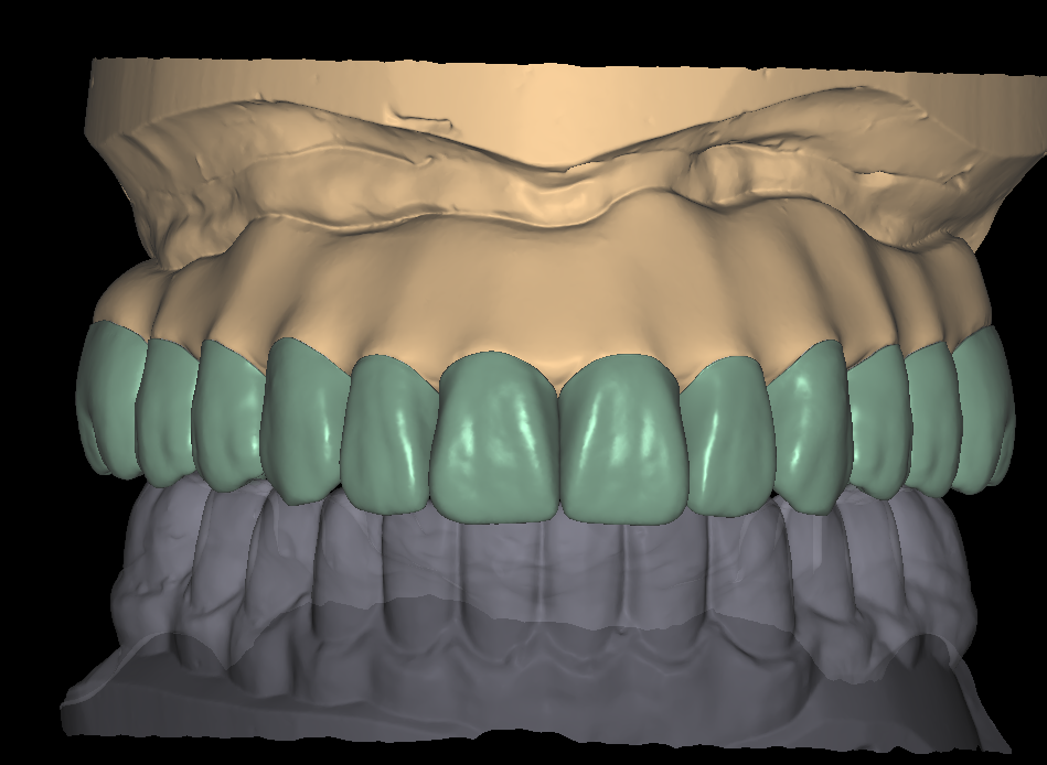
Two failures turn up more than any other on screw-retained work. The first is a wall so thin that the milling unit either chips it or rejects the toolpath. The second is a channel that breaks through the emergence contour, which leaves an open tunnel into the sulcus. Both trace back to the same root cause. The designer shaped anatomy first and measured thickness afterwards, when moving anything takes hours.
A quick section view catches most of it. Slice the design through each implant’s long axis. Then look at what remains on the facial, lingual and occlusal sides. Check the distance from the channel wall to the outside surface too. If that number makes you nervous on screen, it will make your mill nervous as well.
Access Holes, Plugs and Retrievability
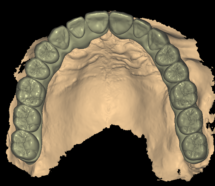
The access hole is the part of a screw-retained restoration that patients and clinicians both see. Place it in the central fossa or the cingulum and it disappears into the anatomy. Place it a millimetre off and it catches light every time the patient speaks. Designers therefore plan the exit point while the occlusal scheme is still flexible, not after the cusps are final.
Size matters as much as position. A hole wide enough for the driver, with a clean chamfer, accepts a composite plug that stays put. A hole that is too tight forces the clinician to enlarge it chairside. That chairside work damages the margin of the plug seat. Leave a small recess for the plug material as well, so the repair sits level with the occlusion instead of proud of it.
Torque Values the Lab Should Not Guess
Torque belongs to the implant system, never to the design file. The manufacturer publishes a value for each platform and interface, and that number assumes clean threads and a seated restoration. A laboratory that tightens to habit rather than protocol can strip a screw seat. The designer worked hard to protect that seat. The screw thread geometry differs between systems, so a value carried over from another case proves nothing.
Two habits keep this side of the process honest. Write the torque value and driver type into the construction information you send with the file. Then note the sequence for multi-unit cases. Tightening one screw fully before the others can tilt a passively fitting bridge, which then needs reworking at the chair. A short written protocol removes the guesswork for whoever seats the case.
A Screw-Retained Crown Design Checklist
Run these checks before any screw-retained file leaves your studio. Each one takes seconds, and each one has caused a remake somewhere.
- Channel planned before anatomy, with the exit point marked on the occlusal or lingual surface
- Angulation inside the correction system’s stated range, or the case moved to cement retention
- Ti-base seat, anti-rotation and bonding gap verified against the library in use
- Material thickness checked in section view on facial, lingual and occlusal surfaces
- Access hole sized for the driver, with a chamfer and a recess for the plug
- Torque value, driver type and tightening sequence written into the construction information
Most of these checks take less time than a phone call, and every one of them saves more than a remake. Labs that outsource screw-retained work can hand the list to a partner as part of the prescription. Doing so removes the polite ambiguity that surrounds phrases like “as thin as possible”. A number beats an adjective every time.
At OdontaLab, every screw-retained crown and bridge design starts with the channel. From there we build on stock Ti-bases, multi-unit abutments or custom abutments, and verify the interface before export. Designs return within 12-24 hours of a complete case, in exocad or 3Shape. Rush work carries no surcharge, because urgent cases are the reason a design partner exists. The rest of the range sits on the design services page, including custom abutments for cases where correction will not work.
If a case is sitting on your bench right now with an awkward angle, that is the one worth testing. Send the verified scan and the implant details through our contact page. We will confirm the channel strategy and the delivery window before anyone starts designing. One real case tells you more than any brochure, and it settles the question the same week.